 Skip to content
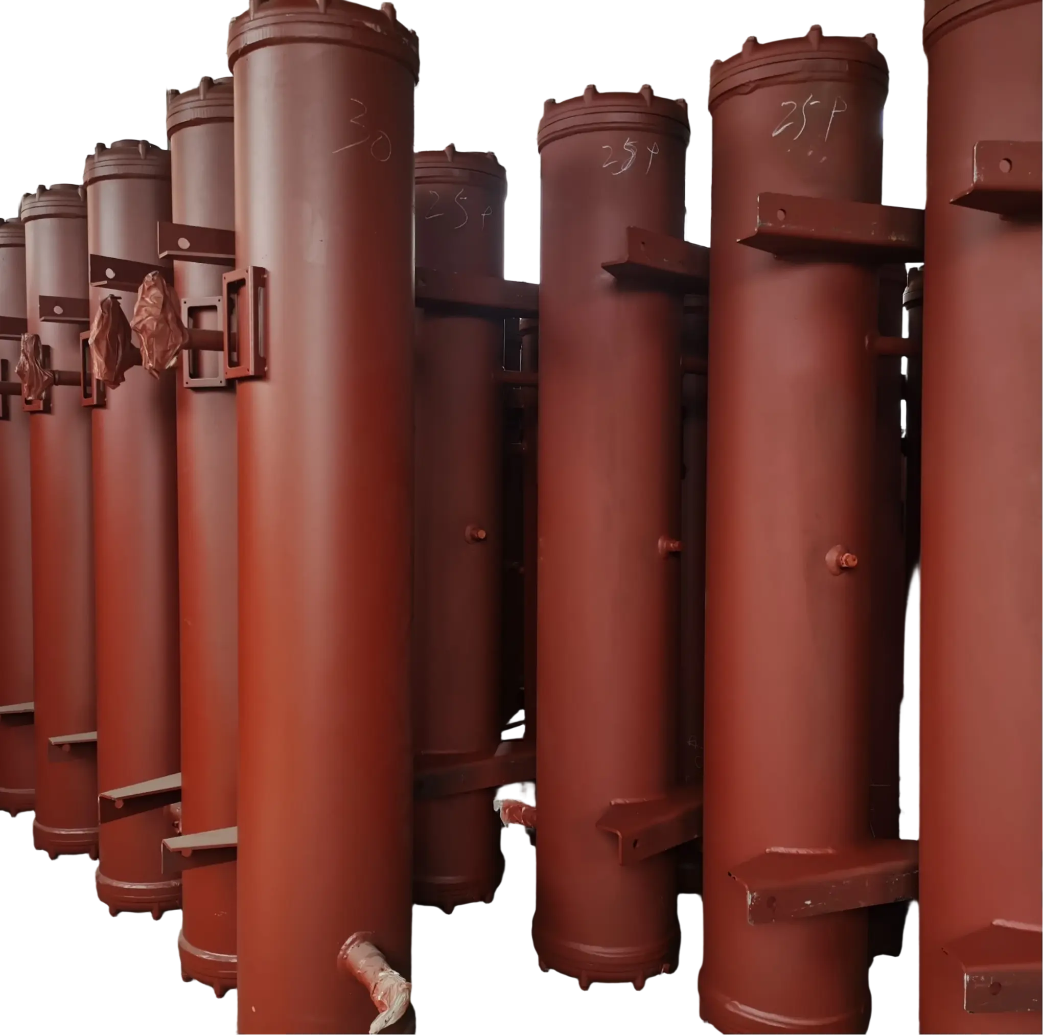

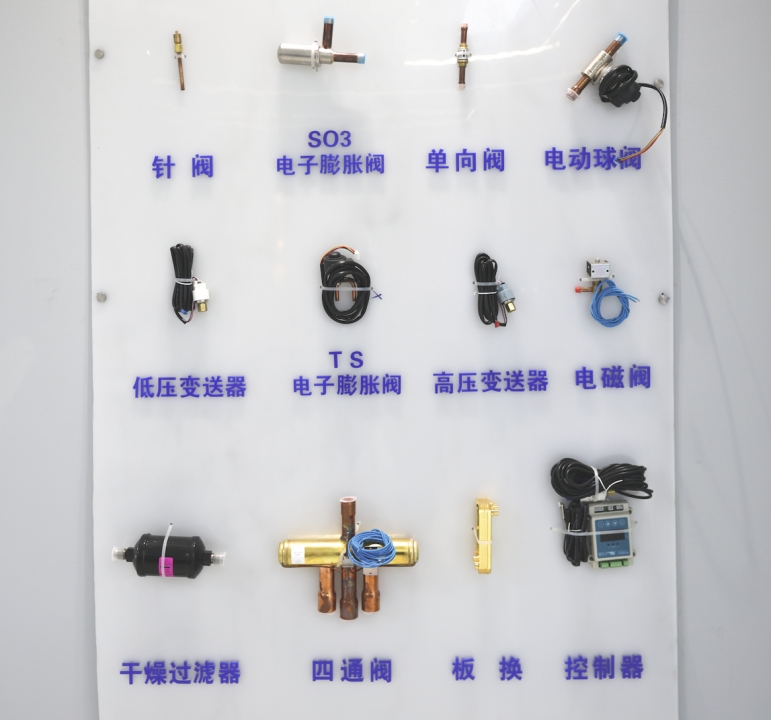

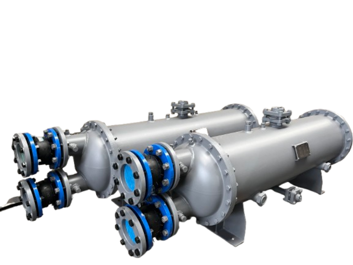
The shell and tube heat exchanger is one of the most widely used heat transfer devices in industrial applications. It is designed to efficiently transfer thermal energy between two fluids while keeping them physically separated. Thanks to its reliability, flexible design and ability to withstand high-pressure and high-temperature conditions, it has become the go-to solution in sectors such as oil and gas, chemical processing, power generation, HVAC, food processing and marine engineering.
The working principle is based on indirect heat transfer. Rather than mixing the fluids, the exchanger uses a solid metal barrier — typically made from materials such as stainless steel, carbon steel, titanium or copper alloys — to transfer heat from one fluid to another.
The basic process is simple:
- One fluid flows through the internal tubes.
- The second fluid then flows around the outside of the tubes, inside the shell.
- Heat moves through the tube wall from the hotter fluid to the colder fluid.
- The heated or cooled fluids then leave the exchanger to continue to the next stage of the industrial process.
While the operating concept is straightforward, designing and optimising the performance of a shell and tube heat exchanger involves complex engineering calculations relating to fluid dynamics, heat transfer coefficients, pressure drop, and material selection.
What Is a Shell and Tube Heat Exchanger?
A shell and tube heat exchanger consists of a large cylindrical shell containing multiple tubes arranged in a bundle. The tube bundle provides a large heat transfer surface area while maintaining separation between two fluid streams.
The main components include:
| Component | Function |
| Shell | Provides an external passage for one fluid and supports the tube bundle |
| Tubes | Transfer heat between two fluids through the tube wall |
| Tube sheets | Hold and seal the tubes at both ends |
| Baffles | Guide shell-side fluid flow and improve heat transfer |
| Tube-side headers | Direct fluid into and out of the tubes |
| Pass partitions | Control fluid flow direction through multiple passes |
The design can be customized according to operating requirements. For example, a chemical plant may require corrosion-resistant materials, while a power station may need a large exchanger capable of handling extremely high flow rates.
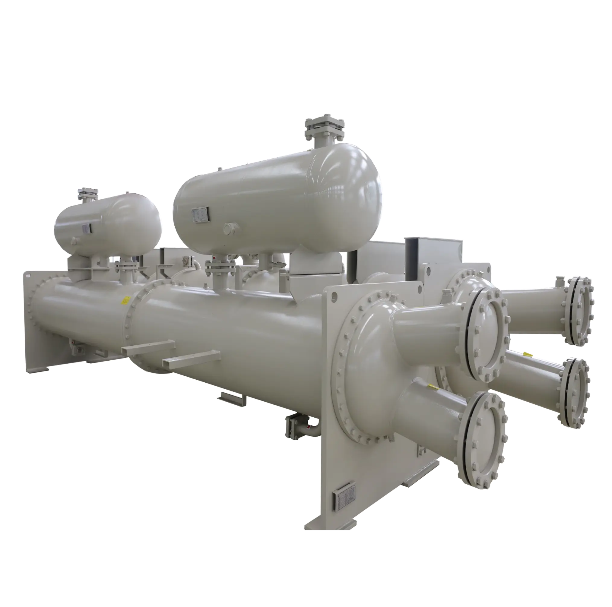
The Basic Working Process of a Shell and Tube Heat Exchanger
The operation of a shell-and-tube heat exchanger involves several continuous steps.
-
Hot fluid enters the heat exchanger
The hot fluid enters either the tube side or the shell side, depending on the design requirements. Engineers determine the flow arrangement based on factors such as:
- Fluid pressure
- Temperature level
- Corrosion characteristics
- Fouling tendency
- Required heat transfer efficiency
For example, fluids with higher pressure are often placed inside tubes because tubes can withstand pressure more efficiently than large shell structures.
-
Cold fluid flows through the opposite channel
The second fluid enters through a separate inlet and flows through the opposite side of the exchanger.
The two fluids never come into direct contact with each other. Instead, heat transfers through the tube material that separates them.
This indirect transfer method provides several advantages:
- Prevents contamination between fluids
- Allows processing of hazardous materials
- Improves operational safety
- Enables heat recovery
-
Heat transfer occurs through the tube wall
The actual heat transfer process involves three stages:
Convection from the hot fluid: heat moves from the hot fluid to the inner surface of the tube through convection.
Conduction through the tube material: heat travels through the metal tube wall by conduction.
Convection to the cold fluid: heat transfers from the outer tube surface into the colder fluid through convection.
The efficiency of the entire process depends on the resistance created by each stage.
Flow Arrangements in Shell and Tube Heat Exchangers
The way fluid moves has a significant impact on the performance of a heat exchanger.
The most common configurations are:
-
Parallel flow
Both fluids enter from the same end and move in the same direction.
Advantages:
- Simple design
- Lower thermal stress
Disadvantages:
- Lower heat transfer efficiency
- Outlet temperatures approach each other quickly
-
Counterflow
In a counterflow design, the two fluids move in opposite directions.
This arrangement is widely preferred because it provides higher heat transfer efficiency.
Advantages include:
- Greater temperature difference throughout the exchanger
- Higher thermal effectiveness
- Better energy recovery
Many industrial shell and tube heat exchangers use counter-flow arrangements because they maximise heat transfer performance.
-
Cross flow
In cross-flow designs, one fluid moves perpendicular to the other.
This configuration is common in applications such as air coolers and certain HVAC systems.
Why Are Shell and Tube Heat Exchangers Widely Used?
Shell and tube heat exchangers are popular due to their ability to operate under demanding industrial conditions.
The major advantages are:
-
High temperature and pressure resistance
Compared with many other types of heat exchangers, shell and tube designs can withstand extreme operating environments.
They are commonly used in:
- Refineries
- Chemical plants
- Power stations
- Offshore platforms
-
Flexible design options
Engineers can modify the following:
- Number of tubes
- Tube diameter
- Shell diameter
- Number of passes
- Materials
to meet different process requirements.
-
Easy maintenance
Many shell-and-tube heat exchangers allow tubes to be cleaned, inspected, and replaced, making them suitable for long-term industrial operation.
Types of Shell and Tube Heat Exchangers
Although all shell and tube heat exchangers operate based on the same heat transfer principle, their structures can vary significantly depending on application requirements. The selection of the correct design affects efficiency, maintenance requirements, operating pressure, and service life.
According to the Tubular Exchanger Manufacturers Association (TEMA) standards, shell and tube heat exchangers are commonly classified according to their front head, shell type, and rear head configuration.
The most common designs include:
| Type | Structural Features | Typical Applications |
| Fixed Tube Sheet Heat Exchanger | Tubes are permanently attached to tube sheets at both ends | Chemical plants, general process heating and cooling |
| U-Tube Heat Exchanger | Tubes are bent into a U shape, allowing thermal expansion | High-temperature applications and steam systems |
| Floating Head Heat Exchanger | One tube sheet can move to compensate for expansion | Petroleum refining and heavy industrial processes |
| Double Pipe Heat Exchanger | Simple tube-in-tube structure | Small-scale heating and cooling systems |
-
Fixed Tube Sheet Design
A fixed tube sheet heat exchanger is one of the simplest and most commonly used configurations. The tubes are attached directly to both tube sheets, creating a strong and reliable structure.
Its advantages include:
- Lower manufacturing cost
- Compact design
- Good mechanical strength
However, because the tubes cannot move independently, this design is less suitable for applications involving large temperature differences between the shell and tube sides.
-
U-Tube Design
In a U-tube heat exchanger, each tube bends into a U shape and connects to the same tube sheet.
This design allows the tubes to expand and contract freely when exposed to temperature changes. As a result, it is widely used in systems where thermal stress is a concern.
Common applications include:
- Steam condensers
- Boilers
- High-temperature processing equipment
One limitation is that cleaning the inside of U-shaped tubes can be more difficult compared with straight tubes.
-
Floating Head Design
Floating head shell and tube heat exchangers are designed for demanding industrial environments where frequent temperature changes occur.
The floating tube sheet allows thermal expansion without creating excessive mechanical stress.
These exchangers are commonly used in:
- Oil refineries
- Petrochemical plants
- Large-scale energy facilities
Although they offer excellent flexibility, their structure is more complex and usually requires higher manufacturing costs.
Factors Affecting Shell and Tube Heat Exchanger Performance
The efficiency of a shell and tube heat exchanger depends on several operating and design factors. A properly designed exchanger can significantly reduce energy consumption, while poor operating conditions may lead to performance degradation.
-
Temperature Difference
The temperature difference between the hot and cold fluids is the driving force for heat transfer.
A larger temperature difference generally improves heat transfer capability. However, extremely high temperature differences may create thermal stress and material expansion problems.
Engineers usually calculate the logarithmic mean temperature difference (LMTD) to evaluate exchanger performance.
-
Flow Velocity
Fluid velocity affects both heat transfer efficiency and pressure loss.
Higher velocity can improve heat transfer because it increases turbulence and reduces boundary layers on heat transfer surfaces.
However, excessive velocity may cause:
- High pressure drop
- Tube erosion
- Increased pumping costs
The optimal flow velocity must balance heat transfer improvement and operating cost.
-
Tube Material Selection
The tube material directly influences heat transfer performance, corrosion resistance, and equipment lifespan.
Common materials include:
| Material | Characteristics | Typical Uses |
| Stainless Steel | Corrosion resistance and durability | Chemical processing, food industry |
| Carbon Steel | High strength and economical | General industrial applications |
| Copper Alloy | Excellent thermal conductivity | HVAC and marine systems |
| Titanium | Outstanding corrosion resistance | Seawater applications |
Material selection depends on fluid characteristics, temperature, pressure, and environmental conditions.
-
Fouling and Deposits
Fouling is one of the biggest challenges affecting heat exchanger efficiency.
Over time, materials such as:
- Minerals
- Organic deposits
- Corrosion products
- Biological growth
- can accumulate on tube surfaces.
A fouling layer acts as insulation, reducing heat transfer efficiency and increasing energy consumption.
Regular inspection and cleaning are essential for maintaining performance.
Industrial Applications of Shell and Tube Heat Exchangers
Because of their reliability and adaptability, shell and tube heat exchangers are used across many industries.
-
Oil and Gas Industry
In refineries and petrochemical plants, shell and tube heat exchangers are used for:
- Crude oil heating
- Product cooling
- Condensation processes
- Heat recovery systems
They are especially suitable for high-pressure applications where reliability is critical.
-
Power Generation
Power plants use shell and tube heat exchangers in:
- Steam condensers
- Feedwater heaters
- Cooling systems
Their ability to handle large volumes of fluid makes them ideal for energy production facilities.
-
Chemical Processing
Chemical plants often require precise temperature control during reactions and separation processes.
Shell and tube heat exchangers provide:
- Stable heat transfer
- Chemical compatibility
- Long service life
-
HVAC Systems
In commercial and industrial HVAC applications, they are commonly used for:
- Chilled water systems
- Condensers
- Heat recovery units
-
Food and Beverage Processing
Food processing industries use these exchangers for:
- Heating liquids
- Cooling products
Maintaining hygienic processing conditions
Materials such as stainless steel are commonly selected because they meet cleanliness requirements.
Maintenance Methods for Shell and Tube Heat Exchangers
Proper maintenance extends equipment life and maintains energy efficiency.
-
Regular Inspection
Operators should regularly check:
- Leakage signs
- Pressure changes
- Temperature performance
- Unusual vibration
Early detection prevents expensive failures.
-
Tube Cleaning
Cleaning methods depend on the type of deposits.
Common methods include:
- Mechanical Cleaning
Using brushes, scrapers, or high-pressure water systems to remove deposits.
- Chemical Cleaning
Using specialized cleaning solutions to dissolve scale or chemical buildup.
The correct cleaning method depends on tube material and fouling type.
-
Monitor Performance Data
A gradual decrease in heat transfer performance may indicate:
- Fouling accumulation
- Flow blockage
- Tube damage
- Incorrect operating conditions
Monitoring inlet and outlet temperatures helps identify problems early.
FAQ About Shell and Tube Heat Exchangers
- What is the working principle of a shell and tube heat exchanger?
A shell and tube heat exchanger transfers heat between two fluids through metal tubes. One fluid flows inside the tubes while another flows around the tubes inside the shell. Heat passes through the tube wall without mixing the fluids.
- Why are shell and tube heat exchangers widely used?
They are popular because they can handle high temperatures, high pressures, large flow rates, and demanding industrial conditions. Their flexible design and easy maintenance also make them suitable for many industries.
- What is the difference between shell side and tube side flow?
Tube-side flow refers to fluid traveling inside the tubes, while shell-side flow refers to fluid moving around the outside of the tubes within the shell. Engineers choose the flow arrangement according to pressure, corrosion, and maintenance requirements.
- How can the efficiency of a shell and tube heat exchanger be improved?
Efficiency can be improved by optimizing:
- Fluid velocity
- Temperature difference
- Tube arrangement
- Cleaning frequency
- Material selection
Reducing fouling and maintaining proper operating conditions are also important.
- How often should a shell and tube heat exchanger be cleaned?
Cleaning frequency depends on fluid type, operating conditions, and fouling tendency. Systems handling dirty fluids may require more frequent cleaning, while cleaner applications may operate longer between maintenance periods.
- What causes a shell and tube heat exchanger to lose efficiency?
Common causes include:
- Fouling buildup
- Reduced flow rate
- Tube blockage
- Poor temperature control
- Corrosion damage
Regular monitoring helps identify these problems before they become serious.
Conclusion
A shell and tube heat exchanger transfers heat between two fluids via a tube wall, enabling efficient thermal exchange without mixing the fluids directly. Thanks to its simple operating principle, robust construction, and adaptability, it is one of the most important heat transfer solutions used in modern industry.
The performance of a shell and tube heat exchanger depends on correct design selection, suitable materials, proper flow arrangement, and effective maintenance practices. Factors such as temperature difference, fluid velocity, fouling control, and tube material selection influence the system’s overall efficiency and reliability.
As industries continue to prioritise energy efficiency and sustainable operations, shell and tube heat exchangers remain key technologies for heat recovery, process optimisation, and industrial energy management. Understanding how these systems work enables engineers and operators to select, operate, and maintain equipment more effectively, achieving long-term performance and cost savings.