
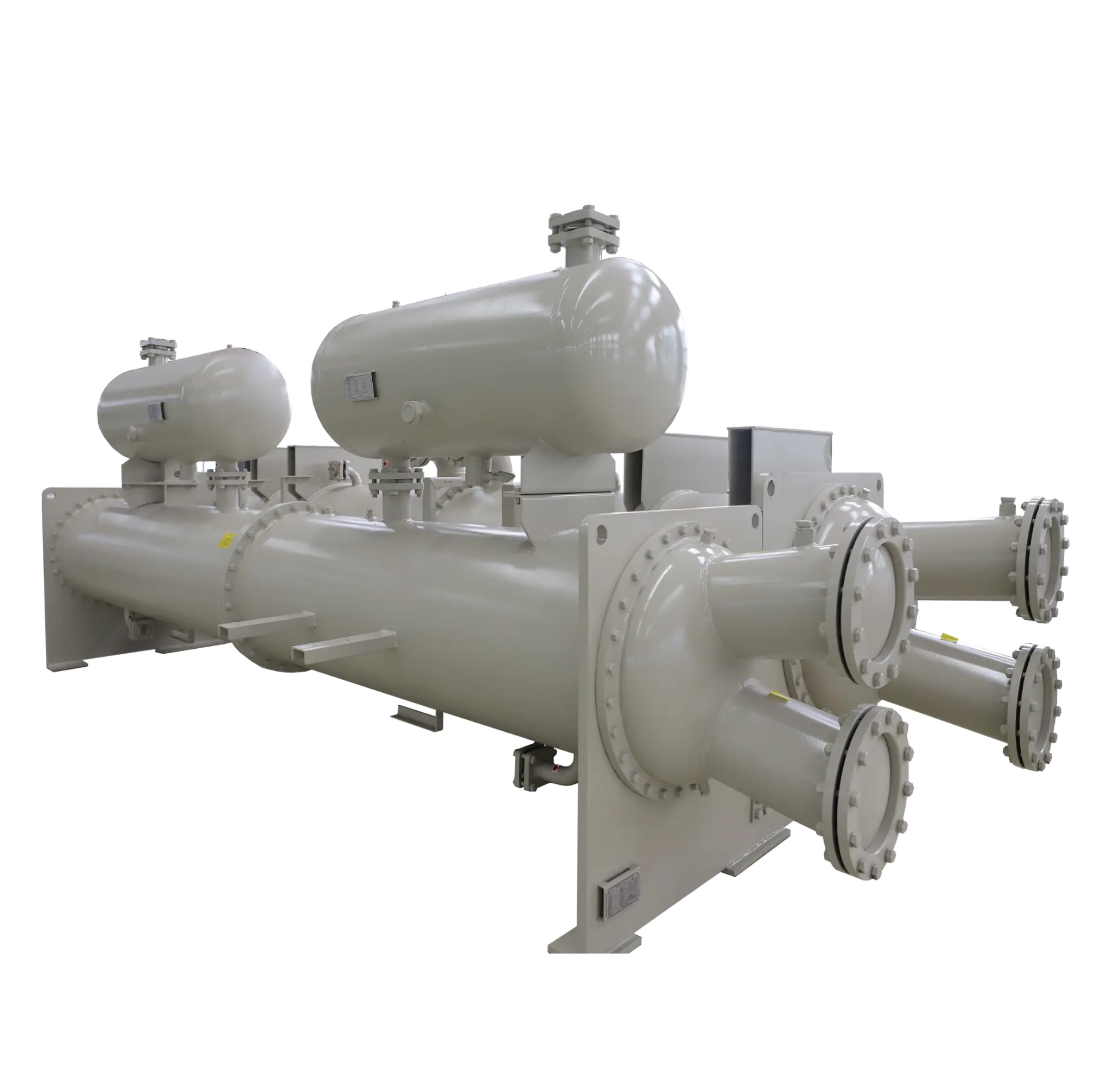

Article Summary: A shell and tube condenser removes heat from vapour by directing it across or through a bundle of tubes carrying a cooler fluid. This allows the vapour to condense into liquid, while the cooling medium absorbs the released heat.
The ASHRAE Handbook: HVAC Systems and Equipment explains that shell-and-tube condensers typically circulate cooling water inside the tubes while the refrigerant condenses outside them. Research on heat exchanger design emphasises the importance of flow arrangement, pressure drop, fouling, and heat transfer area in determining performance.
What Is a Shell and Tube Condenser?
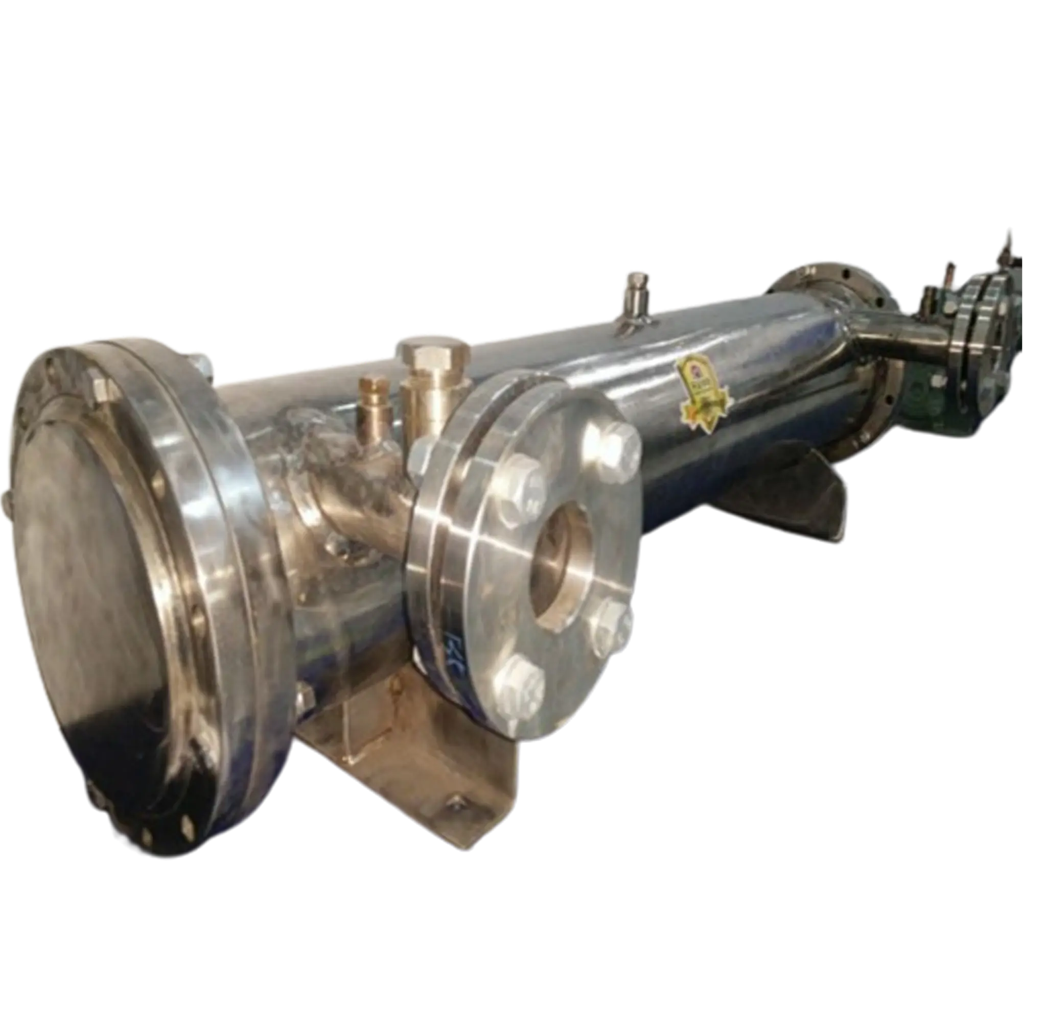
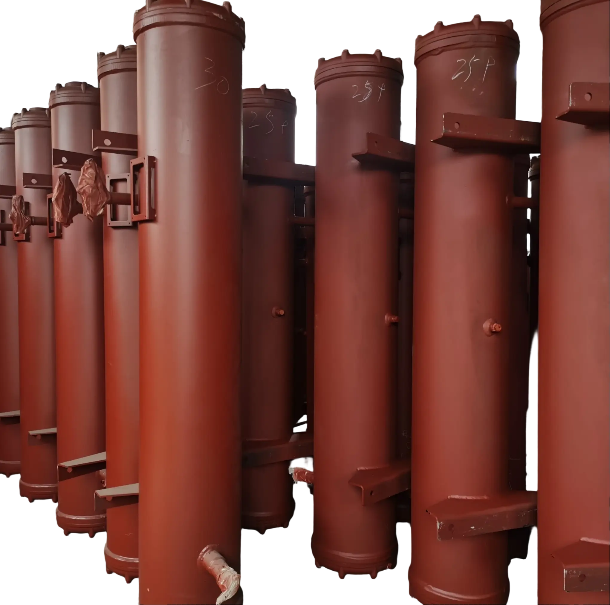
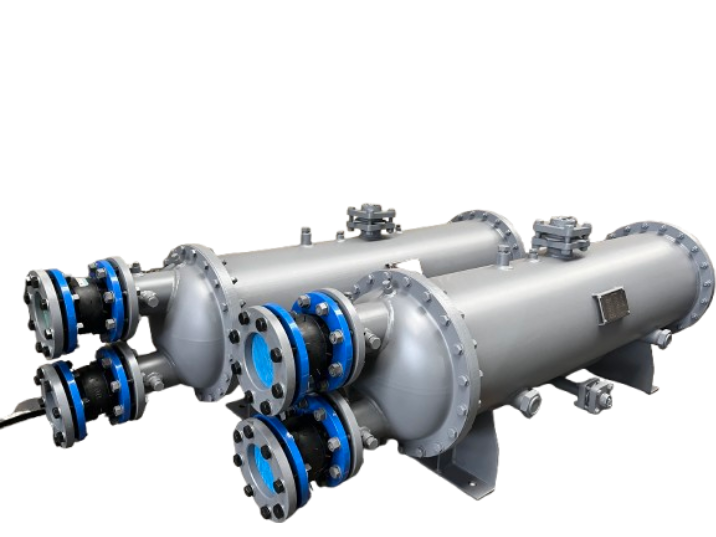
A shell and tube condenser is a type of heat exchanger designed primarily to convert vapour into liquid by removing latent heat. It consists of a cylindrical outer shell, a bundle of tubes, tube sheets, and inlet and outlet connections. Internal components such as baffles and supports are also present. One fluid flows through the tubes while the other occupies the shell-side space. The two fluids remain physically separated by the tube walls, enabling heat to pass from the warmer condensing fluid to the cooler fluid without them mixing directly.
This design is widely used in refrigeration and air conditioning, power generation, chemical processing, petroleum refining, and industrial heat recovery. It is popular due to its ability to handle substantial heat loads, accommodate a broad range of operating pressures and temperatures, and be configured for different process requirements. The Tubular Exchanger Manufacturers Association (TEMA) provides widely used standards for the construction and mechanical design of shell-and-tube exchangers. At the same time, the ASHRAE Handbook describes their role in refrigerant condensation systems.
The key distinction between a condenser and a general-purpose heat exchanger is the phase change that occurs in the hot stream. In an ordinary liquid-to-liquid exchanger, heat transfer generally changes fluid temperatures without altering their physical state. In a condenser, however, vapour releases latent heat as it becomes liquid. Therefore, the process depends on saturation conditions, vapour composition, pressure, cooling-medium temperature, and how efficiently condensate drains from the heat-transfer surface.
How Does a Shell and Tube Condenser Work?
The operating principle is straightforward: a hot vapor stream transfers heat through metal tube walls to a cooler fluid, causing the vapor to condense. The exact flow arrangement depends on the process, but a common industrial configuration sends cooling water through the tubes and refrigerant or process vapor into the shell. As the vapor contacts the cooler tube surfaces, it loses energy, forms a liquid film, and drains toward the condenser outlet.
Step 1: Hot vapor enters the condenser
The vapor enters through a designated inlet nozzle and is distributed through the shell or tube circuit, depending on the design. In a refrigerant condenser, the vapor is typically at a pressure and temperature that allow it to reject heat to the cooling medium. In process applications, the inlet may contain a mixture of condensable vapor and non-condensable gases, which makes flow distribution and gas removal especially important.
Step 2: Heat transfers across the tube walls
The cooling fluid flows through the tubes, absorbing heat from the warmer stream on the opposite side. Heat passes through several resistances: convection from the condensing vapor to the tube surface, conduction through the tube wall, and convection from the tube wall to the cooling fluid. Deposits or scale on either side add thermal resistance, reducing the overall heat transfer rate. Tube material, wall thickness, surface condition, fluid velocity, and temperature difference all influence performance.
Step 3: Vapor changes into liquid
When the vapor contacts a sufficiently cool surface, it releases latent heat and condenses. For a pure substance at a given pressure, condensation occurs near its saturation temperature; mixtures can condense across a temperature range because their components have different volatilities. The resulting liquid forms a film or droplets on the heat-transfer surface, depending on surface properties and operating conditions, and this liquid must drain without obstructing vapor flow.
Step 4: Cooling fluid carries heat away
As cooling water or another coolant absorbs energy, its temperature rises. The cooling system must remove this heat elsewhere, such as through a cooling tower, dry cooler, or another heat-rejection unit. If the cooling fluid enters too warm, its flow is insufficient, or its passages become fouled, the condenser may struggle to reach the required condensing pressure or outlet condition.
Step 5: Condensate leaves the equipment
The condensed liquid exits through a designated outlet and is directed to the next process stage, such as a receiver, storage vessel, recovery system, or refrigeration circuit. Correct nozzle placement, shell orientation, drainage geometry, and operating level help prevent liquid accumulation or vapor carryover. The complete process therefore depends not only on heat transfer but also on stable flow distribution and reliable separation of liquid from vapor.
Main Components and Their Functions
A shell-and-tube condenser performs reliably when each component is designed to withstand the thermal, hydraulic, and mechanical demands of its intended application. The shell contains the shell-side fluid and supports the tube bundle, while the tubes provide the primary heat-transfer surface. The tube sheets then secure the tubes and separate the two fluid circuits. Baffles direct the flow of the shell-side fluid across the tube bundle, reduce bypassing, and provide mechanical support. However, their arrangement must balance heat transfer against the risk of pressure drop and vibration. Channels and heads distribute the tube-side fluid, while nozzles connect the condenser to external piping.
Design details depend on whether the unit is intended for refrigeration, steam condensation or process vapour recovery. For example, a refrigerant condenser may prioritise low pressure drop, dependable liquid drainage and efficient heat rejection. In contrast, a chemical process condenser may require special alloys, corrosion allowances and provisions for removing non-condensable gases. TEMA’s design framework classifies exchanger configurations by front head, shell type and rear head, providing engineers with a systematic approach to specifying construction and maintenance access.
| Component | Primary function | Important design consideration |
| Shell | Encloses the shell-side fluid and tube bundle | Design pressure, temperature, corrosion resistance, and flow distribution |
| Heat-transfer tubes | Transfer heat between the two fluids | Material, diameter, wall thickness, length, fouling, and cleanability |
| Tube sheets | Anchor tubes and separate the fluid circuits | Tube-to-sheet joint integrity and differential thermal expansion |
| Baffles or supports | Direct flow and support the tube bundle | Heat transfer, pressure drop, vibration, and bypass flow |
| Channel and heads | Distribute fluid through the tube passes | Flow balance, pressure containment, and access for inspection |
| Inlet and outlet nozzles | Connect the condenser to process piping | Correct sizing, fluid distribution, drainage, and pressure loss |
| Gaskets and seals | Prevent leakage at removable joints | Chemical compatibility, temperature rating, and maintenance requirements |
| Condensate outlet | Removes the liquid produced by condensation | Adequate drainage, liquid sealing where required, and avoidance of vapor carryover |
Common Types of Shell and Tube Condensers
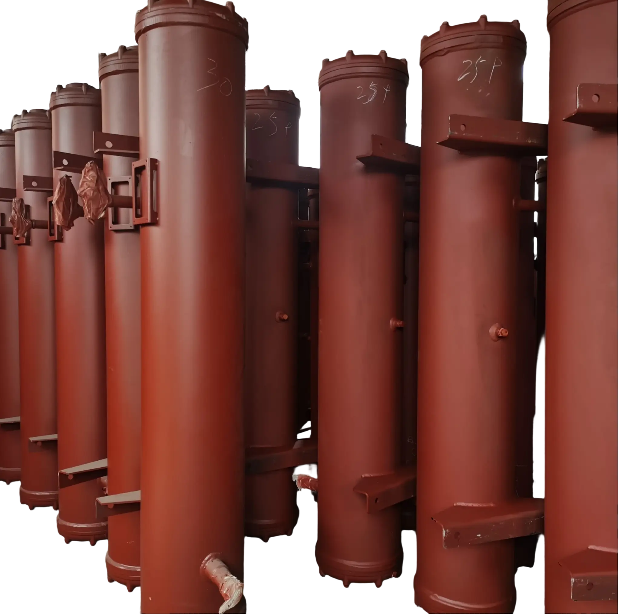
Shell and tube condensers are available in several configurations, and the most suitable type depends on the condensing fluid, operating pressure, cooling medium, maintenance strategy, and available installation space. In many refrigeration systems, horizontal units condense refrigerant on the shell side while cooling water flows through the tubes. Other applications route vapor through the tubes or use vertical configurations to meet process, drainage, or space requirements. There is no single arrangement that is best for every service.
- Water-cooled refrigerant condenser: Cooling water circulates through the tubes while refrigerant condenses on the shell side. This arrangement is common in chillers and industrial refrigeration systems where a separate water circuit can reject heat to a cooling tower or other heat sink.
- Steam condenser: Steam releases latent heat to a cooling stream, producing condensate for discharge or recovery. In power and process facilities, maintaining the required pressure, managing air ingress, and removing condensate are central to performance.
- Process vapor condenser: Chemical, petrochemical, or other process vapors condense as they transfer heat to a coolant or process stream. Material compatibility, mixed-vapor behavior, fouling, and non-condensable gases can have a strong influence on design.
- Partial condenser: Only part of the incoming vapor is condensed, leaving a vapor-rich outlet stream. Partial condensation can support product separation or heat recovery, but it requires careful analysis of vapor composition, temperature, and phase equilibrium.
The term “shell and tube condenser” therefore describes a family of equipment rather than one fixed geometry. A useful selection begins with the required duty and outlet conditions, then establishes which fluid should pass through each side, how the condensate will drain, and what maintenance access is necessary. The ASHRAE Handbook provides practical descriptions of shell-and-tube condensers in refrigeration service, while specialist design literature examines configurations such as TEMA J-shell units for partial condensation with non-condensable gases.
Factors That Affect Condenser Performance
A shell and tube condenser should be evaluated as part of the complete cooling or process system, because its performance depends on both sides of the heat exchanger and the conditions around it. The following factors are especially important during equipment selection, commissioning, and troubleshooting.
- Cooling-medium temperature and flow rate: Cooler inlet water generally provides a greater temperature difference for heat transfer, while inadequate flow can reduce heat removal and increase local fouling risk. Increasing flow is not always the best solution, however, because it may raise pumping power and pressure drop.
- Condensing pressure and vapor conditions: Condensing temperature is closely related to pressure for a pure refrigerant or vapor. In refrigeration, an unexpectedly high condensing pressure can indicate inadequate cooling, fouled tubes, restricted airflow or water flow elsewhere in the system, or the presence of non-condensable gases.
- Heat-transfer surface condition: Scale, deposits, and biological growth create resistance between the process vapor and cooling fluid. Appropriate water treatment, inspection, and cleaning schedules help preserve heat-transfer capacity.
- Flow distribution and drainage: Uneven vapor distribution can leave parts of the tube bundle underused, while poor drainage can allow condensate to accumulate and reduce effective performance. Correct nozzle placement, baffle design, installation orientation, and condensate outlet sizing help limit these problems.
- Material selection and corrosion: The tubes, shell, tube sheets, and sealing materials must withstand the chemistry and temperature of the fluids they contact. Cooling-water chemistry and the composition of the first condensate can be particularly important where corrosive compounds concentrate in the liquid phase.
A useful performance assessment compares actual operation with the original design basis. Relevant measurements include vapor inlet conditions, condensing pressure or temperature, coolant inlet and outlet temperatures, flow rates, pressure drops, and condensate outlet conditions. Looking at these values together helps distinguish a heat-transfer problem from a flow restriction, a cooling-system issue, or an operating condition that has changed since the equipment was commissioned.
Common Problems and How to Troubleshoot Them
Condenser problems often appear first as rising condensing pressure, lower cooling capacity, an abnormal temperature difference, or an increase in energy consumption. The same symptom can have several causes, so operators should verify process measurements before deciding that the heat exchanger itself is faulty. Any inspection or maintenance involving pressurized equipment must follow the site’s isolation, depressurization, and safety procedures.
| Symptom | Possible causes | Recommended checks |
| High condensing pressure | Warm cooling water, low coolant flow, fouled tubes, or non-condensable gases | Check coolant temperatures and flow, inspect pressure trends, and verify gas-removal arrangements. |
| Reduced heat rejection | Scale, deposits, poor flow distribution, or inadequate heat-transfer area | Compare operating data with the design basis and assess fouling or changes in process load |
| Excessive pressure drop | Blocked passages, deposits, high flow, or an unsuitable flow arrangement | Measure pressure drop on both circuits and inspect strainers and accessible passages |
| Corrosion or leakage | Incompatible materials, damaged tubes, failed tube-to-sheet joints, or gasket deterioration. | Conduct an approved inspection and appropriate pressure or leak testing |
| Unstable condensate discharge | Poor drainage, incorrect operating level, or outlet restriction | Check the condensate path, installation orientation, outlet arrangement, and any required liquid seal |
| Recurring fouling | Poor coolant quality, unsuitable water treatment, or contamination in the process stream | Review fluid quality, cleaning intervals, and the root cause of deposit formation. |
Cleaning should be based on the actual fouling mechanism and equipment materials, not on a universal chemical or mechanical procedure. Tube brushing, flushing, or chemical cleaning may be appropriate in different situations, but the selected method must be compatible with tube materials, deposits, seals, and operating requirements. After maintenance, inspect the relevant joints and verify operating performance under controlled conditions before returning the condenser to normal duty.
How to Choose a Shell and Tube Condenser?
Rather than choosing equipment by size alone, selecting a condenser requires a clear definition of the process. Before requesting a quotation, prepare a process specification covering the vapour composition and mass flow, inlet pressure and temperature, target condensation or outlet conditions, coolant type and temperatures, allowable pressure drops and expected fouling. The specification should also include the design pressure and temperature, applicable codes, corrosion requirements, installation constraints and maintenance requirements.
Next, compare the proposed thermal design and mechanical construction. Ensure that the exchanger can fulfil the required duty across realistic operating conditions, not just at one idealised design point. Review the selected tube and shell materials, flow arrangement, condensate drainage, venting requirements, access for cleaning and provisions for inspection. For industrial equipment, TEMA standards are an important reference for mechanical design and construction. However, the applicable pressure vessel codes, project specifications, and local regulations must also be considered for the particular installation.
Finally, consider the total cost of ownership. While a unit with a lower purchase price may be more appealing, it could require more frequent cleaning, consume more pumping power, or be difficult to maintain. Conversely, a more robust design could reduce downtime in the event of severe corrosion or fouling. A more realistic basis for selection than comparing initial equipment prices alone is provided by comparing energy use, service access, spare parts, expected operating hours, and maintenance costs.
Shell and Tube Condenser FAQs
- What is the main purpose of a shell and tube condenser?
Its main purpose is to remove heat from vapor so that the vapor changes into liquid. The released heat is transferred to a separate cooling fluid through the tube walls.
- Which fluid flows through the tubes in a shell and tube condenser?
In many water-cooled refrigeration condensers, cooling water flows inside the tubes while refrigerant condenses on the shell side. The arrangement can differ for other applications depending on pressure, fluid properties, corrosion risk, and cleaning requirements.
- What is the difference between a condenser and a heat exchanger?
A heat exchanger is a broad category of equipment that transfers heat between fluids, while a condenser is designed to condense vapor by removing heat. A condenser is therefore a specialized type of heat exchanger that uses a phase change as part of its operation.
- What causes high pressure in a shell and tube condenser?
Common causes include insufficient cooling-water flow, high coolant inlet temperature, fouled heat-transfer surfaces, and non-condensable gases. The correct diagnosis requires checking operating temperatures, flow rates, pressure trends, and the system’s design conditions.
- How can a shell and tube condenser improve energy efficiency?
Maintaining clean heat-transfer surfaces, providing adequate coolant flow, and minimizing unnecessary pressure drop can improve operating efficiency. Correct sizing and regular monitoring also help reduce avoidable energy consumption and unplanned downtime.
- How often should a shell and tube condenser be cleaned?
There is no universal cleaning interval because fouling depends on fluid quality, operating conditions, and the process application. Cleaning should be scheduled according to inspection results, performance trends, and the manufacturer’s maintenance recommendations.
Conclusion
A shell and tube condenser transfers heat from vapour to a cooler fluid via a bundle of tubes, enabling the vapour to condense while the coolant carries away the released energy. Its performance depends on the heat transfer area, temperature difference, flow distribution, pressure drop, condensate drainage, and the condition of the heat transfer surfaces. For industrial users, selecting the correct configuration and materials, applying suitable design standards, and monitoring operating data are vital for achieving reliable condensation, reducing operating costs, and extending equipment service life.