
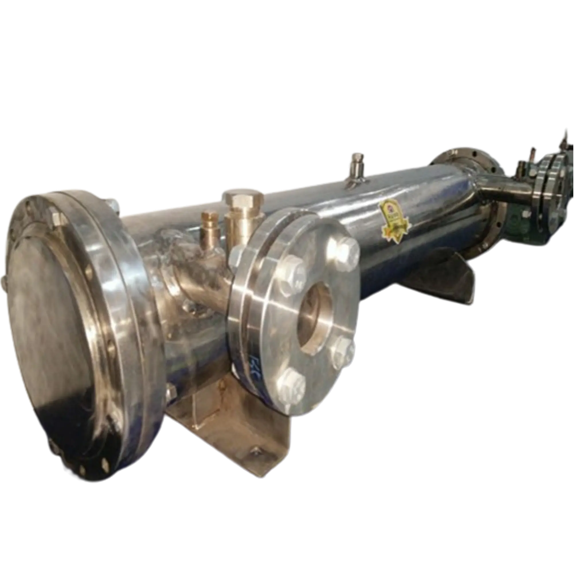
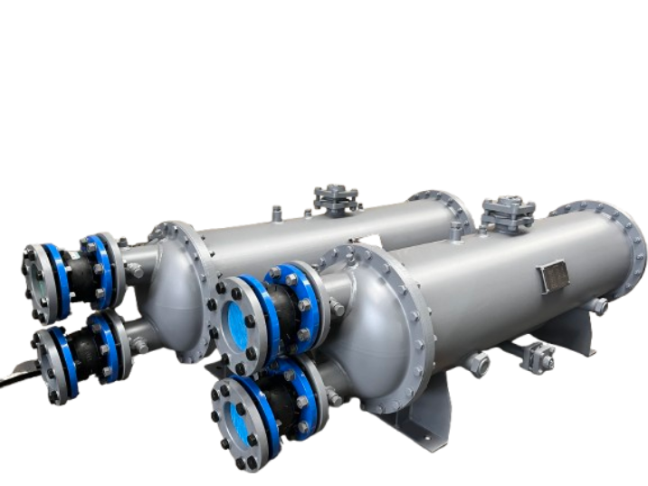
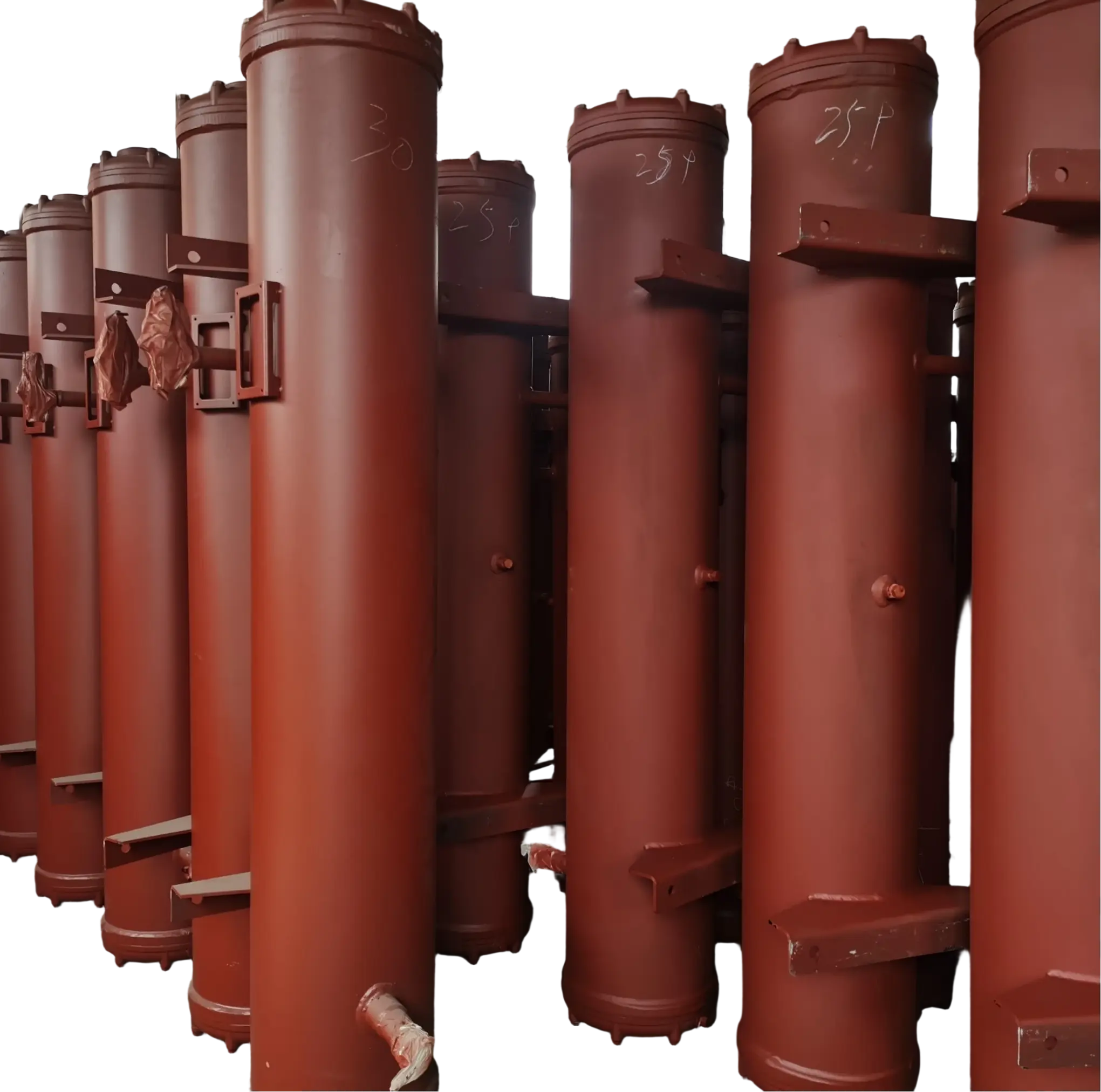
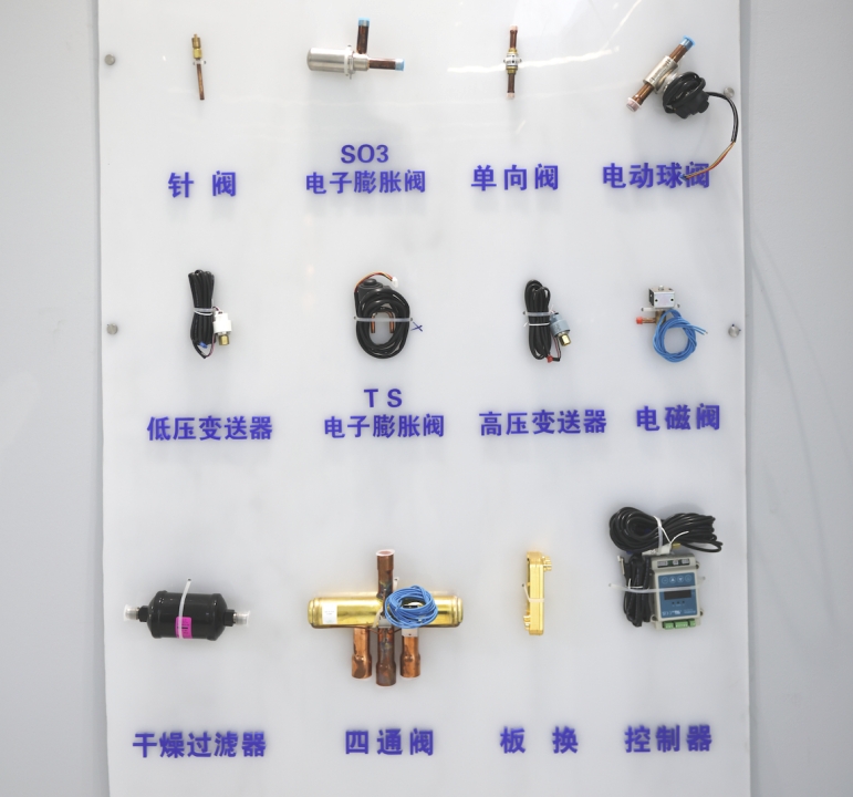
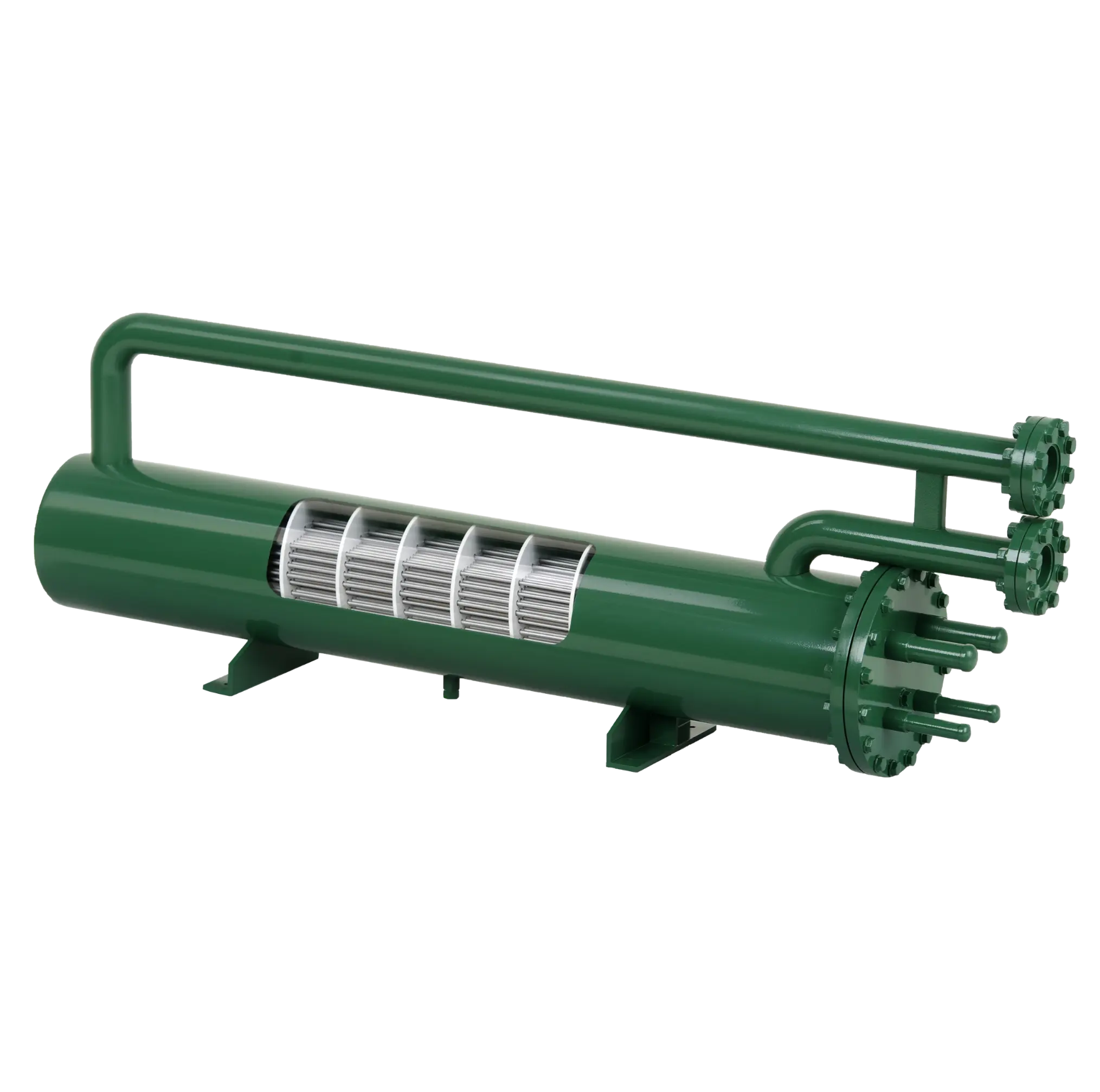

A heat exchanger transfers thermal energy from one fluid to another via a separating surface, or in some designs through direct contact. This allows industrial systems to heat, cool, condense, or recover energy without mixing the two process streams. The performance of a heat exchanger depends on the temperature difference between the fluids, the available heat-transfer area, the flow arrangement, the properties of the fluids, and the resistance created by the exchanger’s walls and any deposits. The ASHRAE Handbook: HVAC Systems and Equipment explains the construction and operating principles of common shell-and-tube and plate heat exchangers. Meanwhile, Fundamentals of Heat and Mass Transfer by Incropera et al. provides an explanation of the underlying principles of conduction and convection that govern heat transfer.
What Is a Heat Exchanger?
A heat exchanger is a piece of thermal equipment designed to transfer heat between two fluids at different temperatures. These fluids may be liquids or gases, or a combination involving a phase change, such as steam condensing into water or a refrigerant evaporating. In many industrial designs, a solid metal wall separates the two streams, enabling heat to pass through the wall while keeping the fluids apart. This separation is essential when the fluids have different chemical compositions, pressures, cleanliness requirements, or safety characteristics.
Heat exchangers are used throughout manufacturing and infrastructure. In chemical plants, for example, they are used to regulate process temperatures and recover heat from hot product streams. In power generation, they support steam cycles and cooling systems. In HVAC systems, they help to condition air and circulate heating or cooling energy. In food processing, they are used to heat or cool products under controlled conditions. While the equipment may look very different from one industry to another, the central engineering task remains the same: to transfer the required amount of heat with an acceptable pressure drop, operating cost, and level of reliability.
The term ‘heat exchanger bank‘ is also used in industrial thermal systems, particularly where multiple tubes, rows, coils, or exchanger modules are arranged together to handle a larger workload. In an air-cooled system, for instance, a heat exchanger bank may comprise rows of bare or finned tubes positioned across an airflow path. In other facilities, the term may describe a group of exchangers arranged in series or in parallel. As usage varies by equipment and industry, the intended configuration should be confirmed in the system drawings and technical specifications.

How Does a Heat Exchanger Work? The Basic Process
A conventional indirect heat exchanger operates in three linked steps. First, heat moves from the hot fluid to the heat-transfer surface by convection. Second, it passes through the solid wall by conduction. Finally, it moves from the wall into the cooler fluid by convection. Depending on the equipment design, the two fluid streams can travel in the same direction, in opposite directions, or across one another. The surfaces and flow passages of the exchanger are arranged to provide sufficient thermal contact while maintaining the required flow rates and pressure limits.
Consider a shell-and-tube heat exchanger used to cool hot process oil with cooling water. The hot oil flows through the shell around a bundle of tubes, while the cooler water flows inside them. Heat passes from the oil to the outer tube surfaces, conducts through the tube walls, and enters the water. The oil leaves at a lower temperature, while the water leaves at a higher temperature. If the equipment is correctly designed and operated, the streams will remain physically separate. The actual temperature change depends on the inlet temperatures, flow rates, heat capacities, the surface area of the exchanger, and the thermal resistance.
The process can be understood through a practical sequence:
- Hot-side inlet: The hotter fluid enters the exchanger and carries thermal energy into the equipment.
- Heat transfer at the surface: Heat moves from the hot fluid to the separating wall through convection.
- Conduction through the wall: Thermal energy travels through the metal or other heat-transfer material.
- Cold-side absorption: The cooler fluid absorbs heat from the opposite side of the wall.
- Outlet temperature change: The two streams leave at different temperatures from their inlets, with the energy balance determined by the heat transferred and any losses to the surroundings.
Not every exchanger follows this exact arrangement. In a direct-contact exchanger, fluids exchange heat while physically contacting one another, and in phase-change equipment, condensation or evaporation can dominate the thermal process. Nevertheless, the distinction between the energy transferred, the resistance to transfer, and the pressure required to move the fluids remains central to performance evaluation.
The Main Heat Exchanger Flow Arrangements
The way the two fluids travel through an exchanger has a significant effect on its thermal performance. Three common arrangements are parallel flow, counterflow, and crossflow. Each can be appropriate for a particular duty, but the best choice depends on the required outlet temperatures, exchanger geometry, fluid properties, and allowable pressure drop.
- Parallel flow: Both fluids enter at the same end and travel in the same direction. The temperature difference is usually greatest near the inlet and decreases along the exchanger, so this arrangement often provides a less favorable temperature profile than counterflow for comparable conditions.
- Counterflow: The fluids enter from opposite ends and move in opposite directions. This maintains a more uniform temperature difference along much of the heat-transfer surface and can allow the cold stream to leave at a temperature higher than the hot stream’s outlet temperature, provided the inlet conditions and heat balance permit it.
- Crossflow: The fluids travel approximately perpendicular to one another. This arrangement is common in air-cooled heat exchangers, vehicle radiators, HVAC coils, and heat exchanger banks in which air flows across rows of tubes carrying a liquid or another process fluid.
A heat exchanger bank demonstrates the importance of considering flow arrangement and geometry together. As air passes across successive tube rows, the temperature and flow pattern of the air changes, affecting the next row. While fins can increase the effective heat-transfer area, tube spacing, row count, and staggered or inline layouts affect both heat transfer and airflow resistance. While a staggered arrangement can improve heat transfer under certain conditions, it can also increase pressure drop and fan power. Therefore, the design target is not simply maximum heat transfer, but rather the required thermal duty at an acceptable combined energy and maintenance cost.
Common Types of Heat Exchangers and How They Work
Different heat exchanger designs solve different operating problems. Shell-and-tube units are widely used for demanding industrial processes, while plate exchangers provide compact heat-transfer surfaces and are ideal where space is limited. Air-cooled units reject or absorb heat using ambient air, while double-pipe exchangers are often used for smaller tasks or specialised processes. The selection process should begin with the requirements of the process rather than assuming that one design is always more efficient.
Common designs at a glance
| Heat exchanger type | How it works | Typical applications | Main considerations |
| Shell-and-tube | One fluid flows inside tubes while the other flows around them within a shell. | Chemical processing, oil and gas, power generation | Robust construction, pressure and temperature requirements, cleaning access |
| Plate heat exchanger | Two fluids flow through alternating channels separated by thin plates | HVAC, food processing, industrial water heating | Compact design, high heat-transfer area, pressure and gasket compatibility |
| Air-cooled heat exchanger | Process fluid flows through tubes while air passes over the tube surfaces, often assisted by fans. | Refineries, process plants, remote cooling installations | Ambient temperature, fan power, noise, fin fouling |
| Double-pipe heat exchanger | One fluid flows through an inner pipe and the other through the surrounding annular passage. | Smaller process duties and specialized services | Modular construction, capacity limits, pressure drop |
| Heat exchanger bank | Multiple tube rows, coils, or exchanger modules work together as a larger thermal assembly. | Boilers, HVAC coils, industrial air cooling, heat recovery | Flow distribution, row geometry, total pressure drop, maintenance access |
Shell-and-tube heat exchangers
A shell-and-tube heat exchanger comprises a bundle of tubes within a pressure-containing shell. Tube sheets secure the tubes in place, and channel heads and partitions direct the flow of the fluid on the tube side. Baffles guide shell-side fluid across the tube bundle and provide mechanical support; however, their design must balance heat transfer with pressure drop, vibration, and erosion risk. Depending on the application, the exchanger may use straight or U-shaped tubes, or a removable bundle, to accommodate thermal expansion and maintenance needs.
These units are often selected for demanding operating conditions involving high pressure, temperature, fluid compatibility, and mechanical durability. They can be configured for various processes, including liquid-to-liquid heat transfer, condensation and reboiling. However, their size and internal construction can make cleaning and inspection more complicated than with some other types of exchangers, particularly when the process fluid fouls the tube surfaces or when access is restricted.
Plate heat exchangers
A plate heat exchanger directs hot and cold fluids through separate channels formed by thin metal plates. The corrugations on the plates increase the surface area and promote mixing within the flow channels, thereby improving convective heat transfer. In gasketed models, the plates can often be separated for cleaning or capacity adjustment. Brazed and welded designs offer an alternative construction option where there are differences in leakage risks, operating conditions, or maintenance needs.
Plate exchangers are often the preferred option when a compact footprint and close temperature approach are important. However, their limitations depend on the design: gasket material can constrain operating temperature and fluid compatibility, while narrow channels can be sensitive to fouling or blockage. A sound selection process considers both thermal performance and practical requirements such as cleaning, inspection and replacement.
Air-cooled heat exchangers and heat exchanger banks
An air-cooled heat exchanger transfers heat between a process fluid flowing inside tubes and ambient air flowing over the tubes’ exterior. Fins are often attached to the tubes to increase the area available for heat transfer, since air generally transfers heat less effectively than many liquids do. Fans may be used to maintain the required airflow, and multiple tube rows are often assembled into a heat exchanger bank to provide sufficient capacity.
The performance of the bank depends on more than just the surface area. Tube diameter, fin geometry, row spacing, airflow distribution, ambient temperature, and fan operating conditions all influence heat output and power consumption. If some sections receive less airflow than others, the bank may deliver less capacity than predicted, even if its total surface area appears adequate. For this reason, airflow uniformity, access for cleaning, and the ability to inspect the fins and tube connections should be considered during the design and maintenance planning process.

What Determines Heat Exchanger Efficiency?
Heat exchanger performance is governed by the available temperature difference, the effective heat-transfer area, and the overall heat-transfer coefficient. A commonly used engineering relationship is:
Q = U × A × ΔT_(LM)
Where:
Q is the heat-transfer rate, typically measured in watts (W).
U is the overall heat-transfer coefficient, which represents the combined resistance to heat transfer across the system.
A is the effective heat-transfer surface area.
ΔT lm is the logarithmic mean temperature difference (LMTD), which accounts for the changing temperature difference between the two fluids along the exchanger.
For multipass exchangers and certain crossflow configurations, a correction factor may be needed when applying the LMTD method. The equation is a useful starting point for design and performance assessment, but it does not replace detailed thermal calculations or manufacturer selection software. Actual performance also depends on flow distribution, fluid properties, fouling, and the operating conditions on both sides of the equipment.
Several practical factors can reduce the heat-transfer rate. Fouling occurs when scale, corrosion products, biological growth, oil deposits, or other materials accumulate on heat-transfer surfaces, increasing thermal resistance and sometimes restricting flow. Insufficient flow may reduce convective heat transfer, while excessive flow can increase pressure drop, pumping costs, erosion, or vibration. In air-cooled heat exchanger banks, dirty fins, fan degradation, recirculation of hot discharge air, and uneven airflow can also impair performance.
It is important to distinguish thermal effectiveness from energy efficiency. An exchanger may achieve the required outlet temperatures while consuming excessive fan or pump power, or it may transfer a large amount of heat at the cost of an unacceptable pressure drop. A complete assessment therefore considers heat duty, outlet temperatures, pressure drop, auxiliary power, maintenance requirements, and the consequences of any leakage between the two streams.
How to Select the Right Heat Exchanger?
The selection of a heat exchanger should be based on a defined process duty rather than a preferred equipment type. Engineers need to establish the heat load, the properties of the fluids involved, the inlet and target outlet temperatures, the operating and design pressures, the allowable pressure drops and the expected operating schedule. They must also determine whether either fluid could corrode, foul, freeze, polymerise or damage the proposed construction materials. All of these details influence not only the thermal performance, but also the size of the equipment, the safety requirements, the cleaning methods and the service life.
The following selection factors are particularly important for industrial buyers and project engineers:
- Thermal duty and temperature approach: Confirm how much heat must be transferred and the minimum practical temperature difference between the two streams. A tighter temperature approach may require more surface area and higher capital expenditure.
- Fluid properties and compatibility: Review viscosity, heat capacity, thermal conductivity, phase behavior, corrosiveness, and the presence of suspended solids. These characteristics influence the exchanger type, channel dimensions, flow velocity, and material selection.
- Pressure drop and auxiliary power: Check the pressure loss on both sides of the exchanger, including the fans or pumps needed to maintain flow. A design that delivers the required heat with lower lifetime energy consumption may be more economical than one optimized solely for purchase price.
- Fouling and maintenance: Evaluate cleaning frequency, access for inspection, spare-part availability, and the consequences of an unexpected shutdown. Fluids with high fouling potential may require wider passages, removable bundles, or a cleaning strategy designed into the system.
- Installation and operating conditions: Account for ambient temperatures, available space, utilities, noise limits, vibration, and future capacity changes. For a heat exchanger bank, the arrangement of modules and airflow paths may be as important as the nominal capacity of each unit.
The final decision should be based on a documented thermal and mechanical evaluation. For critical industrial service, buyers should request the design basis, predicted duty, pressure-drop calculations, material specifications, applicable design codes, inspection requirements, and performance guarantees. Comparing suppliers on a consistent set of operating conditions helps avoid selecting equipment that looks competitive on price but requires excessive energy or maintenance after installation.
Heat Exchanger Maintenance and Troubleshooting
The capacity of a heat exchanger can gradually decrease as deposits accumulate or operating conditions change. Common warning signs include rising outlet temperatures, reduced heat output, increased pressure drop, higher than expected fan or pump power consumption, and leakage between the fluid circuits. As these symptoms do not point to a single cause, troubleshooting should involve comparing current operating data with the original design conditions and the equipment’s historical performance.
Useful maintenance practices include the routine monitoring of inlet and outlet temperatures, flow rates, and pressure drop, as well as the inspection of surfaces and auxiliary equipment. For a heat exchanger bank, inspections may also cover fin cleanliness, fan condition, airflow distribution, vibration, and visible damage to tubes or headers. Cleaning methods must be matched to the material and deposit type; an aggressive chemical cleaner or an unsuitable mechanical tool could damage the heat-transfer surfaces and create a more serious problem than the original fouling.
When performance deteriorates, the maintenance team should first verify the instruments, flow conditions and control settings, as well as the availability of cooling or heating utilities. If the data indicate fouling, leakage, or mechanical damage, the equipment should be assessed in accordance with the manufacturer’s maintenance procedure and applicable site safety requirements. Recording the cause of each performance issue and the corrective action taken helps to establish maintenance intervals based on actual operating experience rather than an arbitrary schedule.

Heat Exchanger FAQs
- How does a heat exchanger work in simple terms?
A heat exchanger transfers heat from a hotter fluid to a cooler fluid through a heat-transfer surface or, in direct-contact designs, through contact between the fluids. This allows a process to be heated or cooled without necessarily mixing the two streams.
- Do fluids mix inside a heat exchanger?
In most indirect heat exchangers, the fluids remain separated by tubes, plates, or another solid surface. Direct-contact heat exchangers are an exception because the fluids exchange heat while physically contacting one another.
- What is a heat exchanger bank?
A heat exchanger bank is an arrangement of multiple tube rows, coils, or exchanger modules that work together to transfer heat. The term is especially common in air-cooled systems, where tube layout, fin area, and airflow distribution affect overall performance.
- What is the difference between a shell-and-tube and a plate heat exchanger?
A shell-and-tube exchanger transfers heat through tubes housed inside a shell, while a plate exchanger uses thin plates to create separate flow channels. Plate designs are often compact, whereas shell-and-tube designs offer considerable flexibility for demanding pressure, temperature, and process conditions.
- What causes a heat exchanger to lose efficiency?
Common causes include fouling, scaling, corrosion, poor flow distribution, inadequate fluid flow, and damaged auxiliary equipment. Monitoring outlet temperatures, pressure drop, and heat duty can help identify performance changes before they cause major operational problems.
- How do I choose the right industrial heat exchanger?
Start with the required heat duty, inlet and outlet temperatures, fluid properties, operating pressures, and allowable pressure drops. Then evaluate material compatibility, fouling risk, maintenance access, energy consumption, installation constraints, and the supplier’s documented performance calculations.
Conclusion
A heat exchanger transfers thermal energy between fluids via a designed heat-transfer path. Its performance is determined by temperature differences, surface area, fluid flow, and thermal resistance. Shell-and-tube, plate, air-cooled, and double-pipe designs all use this principle, albeit in different ways. A heat exchanger bank, meanwhile, combines tube rows, coils or modules to meet larger thermal requirements.
For industrial users, selecting a suitable exchanger requires more than just comparing nominal capacity or equipment price. A reliable design must balance heat duty, pressure drop, energy consumption, fouling behaviour, material compatibility and maintenance access. Understanding these factors enables engineers and procurement teams to select equipment that meets process requirements and remains dependable throughout its operating life.