
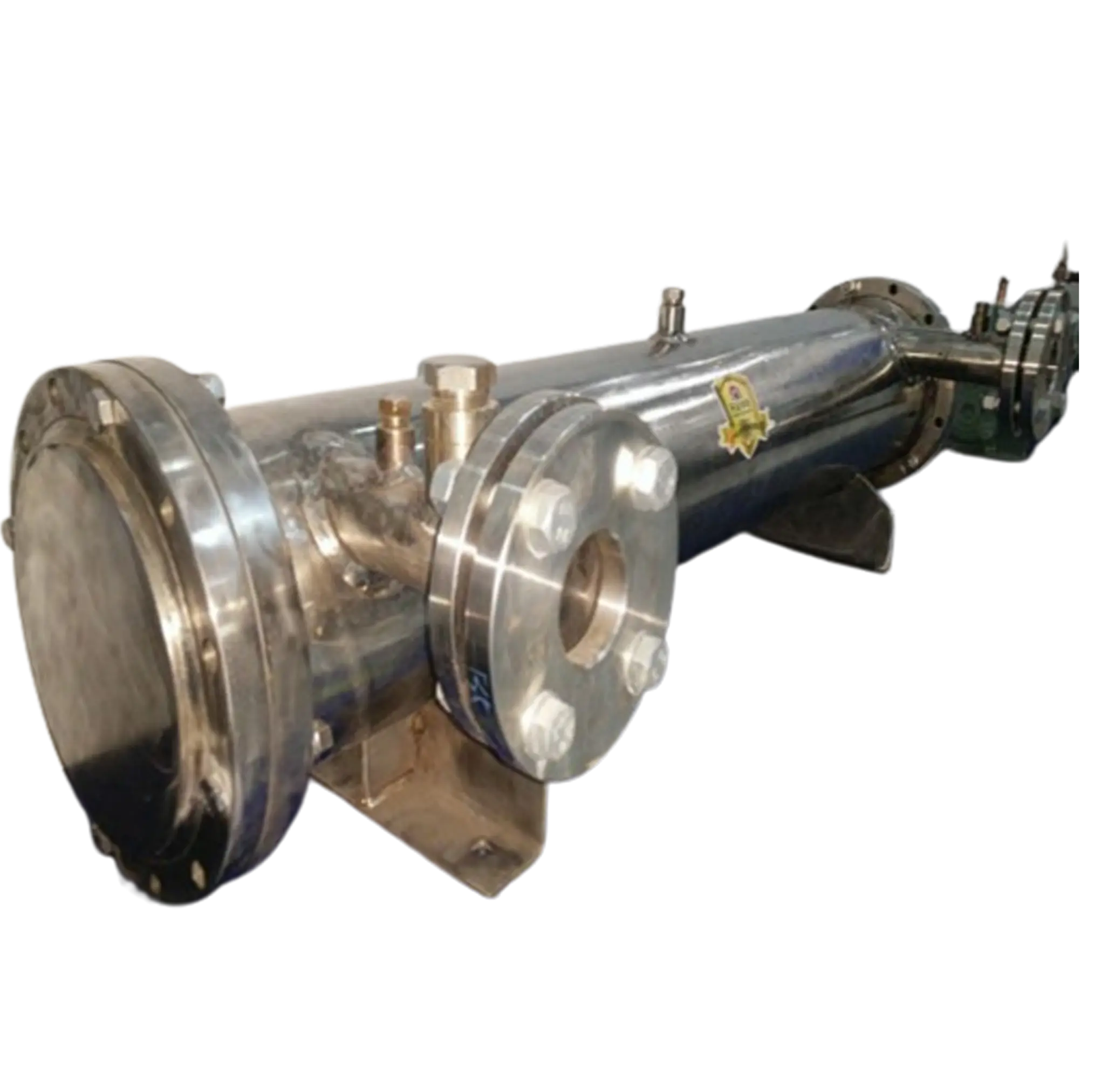
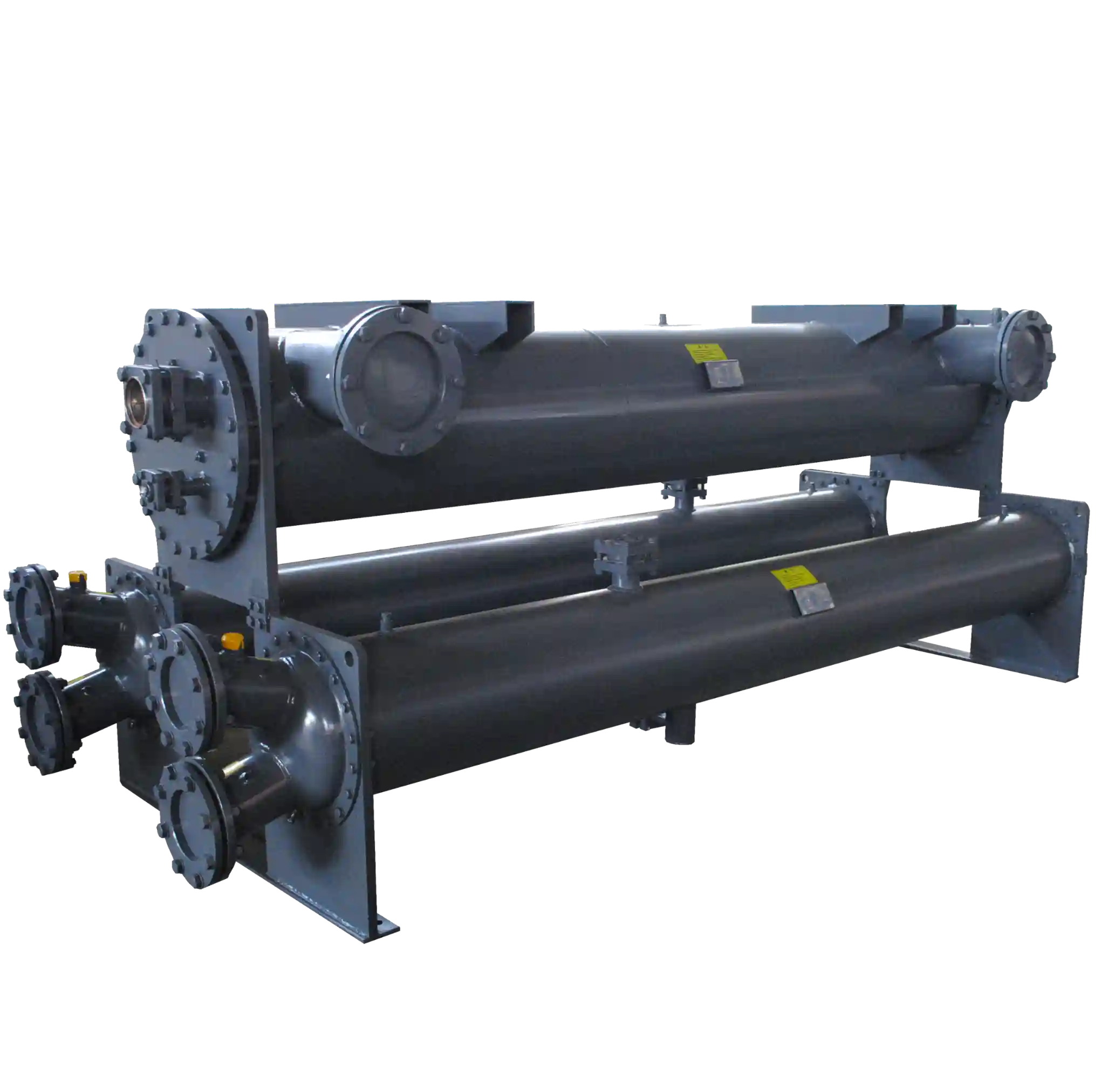
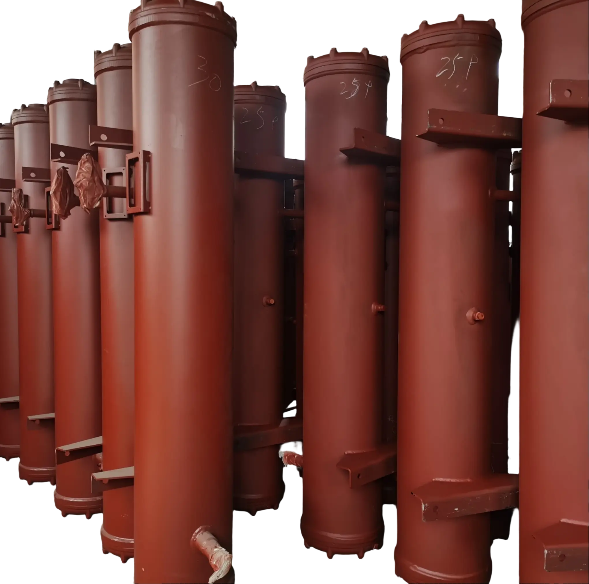
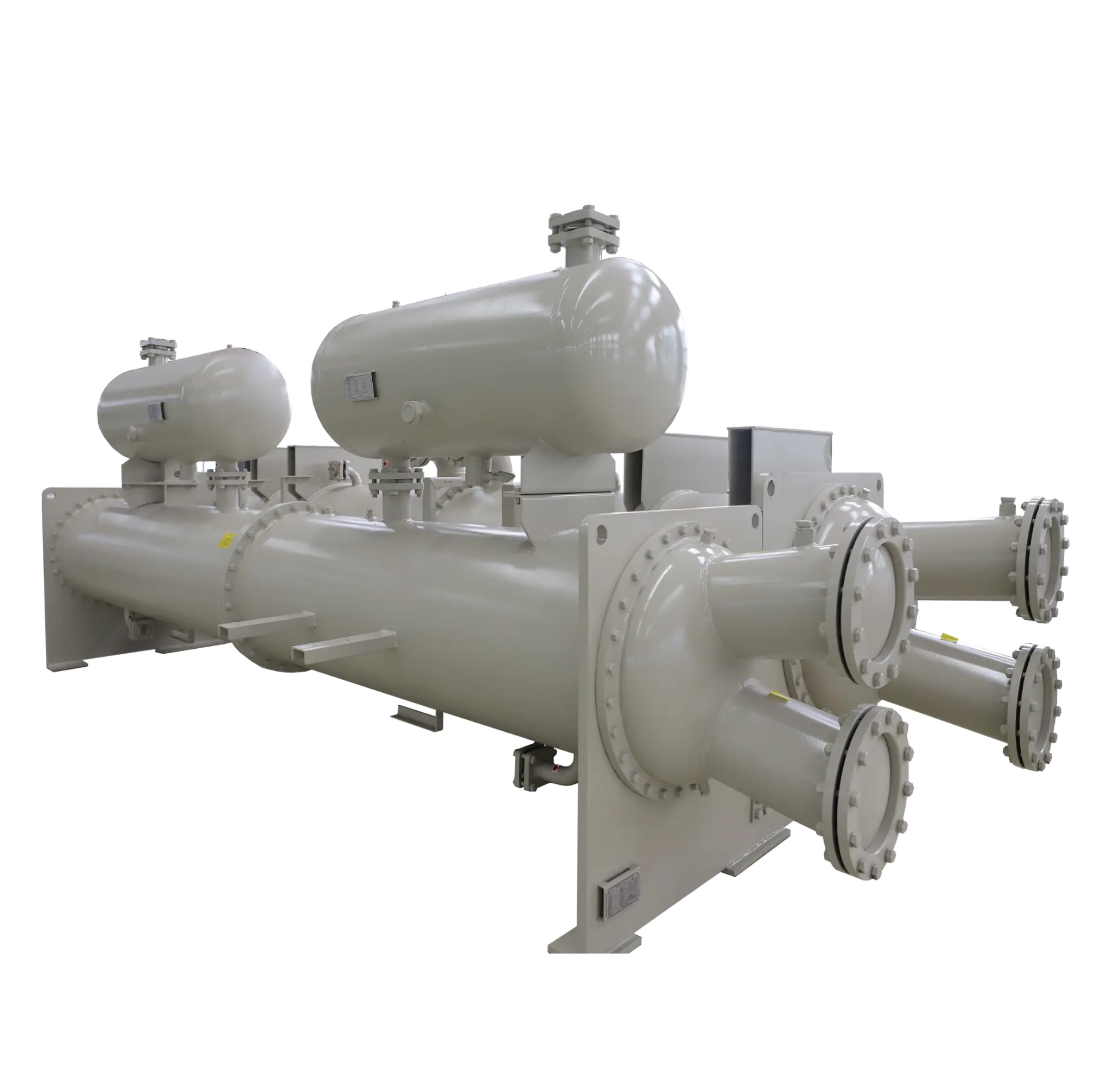
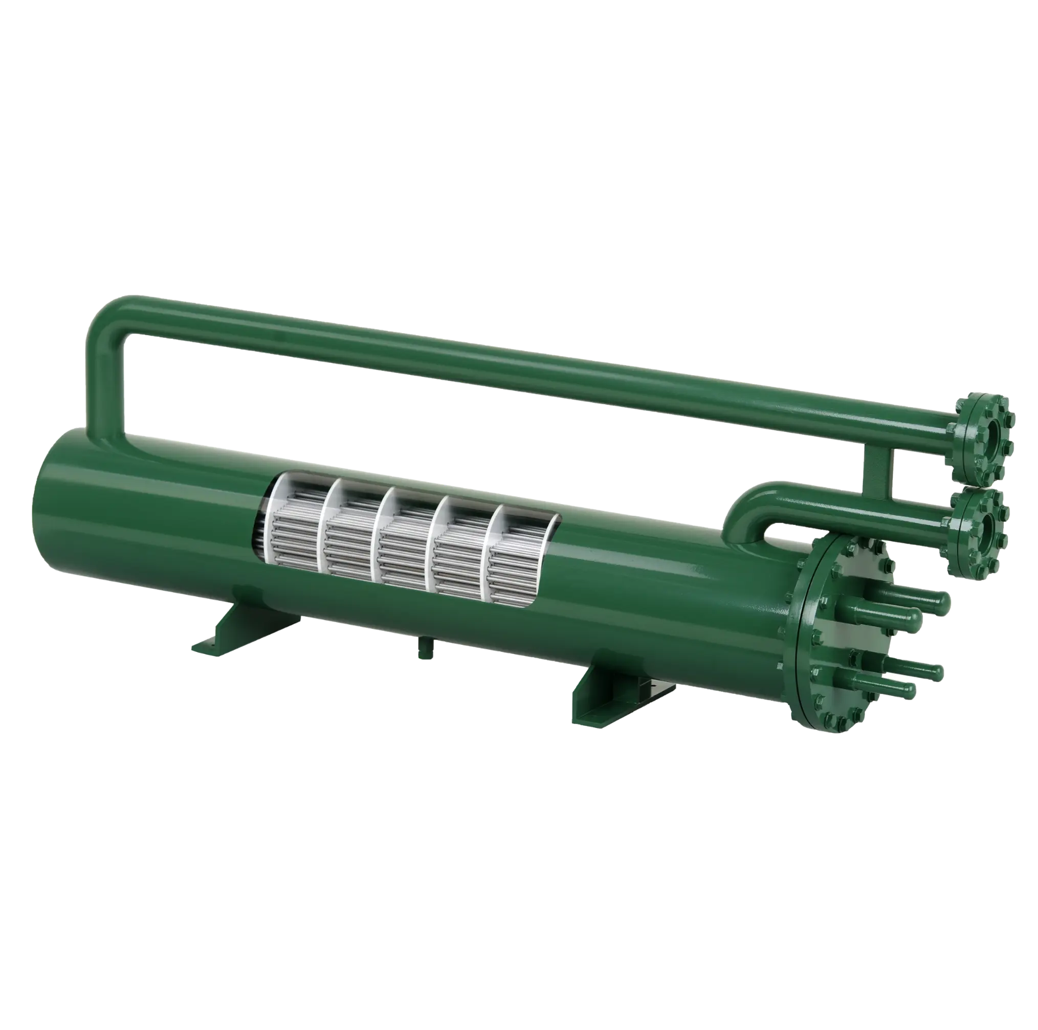

The five most common types of heat exchanger are shell-and-tube, plate-and-frame, double-pipe, spiral and air-cooled. As Ramesh K. Shah, Alfred C. Mueller and Dusan P. Sekulic explain in their engineering reference book, Heat Exchangers: Fundamentals and General Design Methodology, heat exchanger designs differ in terms of the geometry of the heat-transfer surface, the arrangement of the fluid flow, the pressure capability and the suitability for particular operating conditions.
The purpose of a heat exchanger is to transfer thermal energy between two fluids, either through a separating surface or, in direct-contact designs, by bringing the fluids into contact. The optimal design depends on factors beyond heat-transfer efficiency; engineers must also consider operating pressure and temperature, fluid cleanliness, corrosion, available installation space, maintenance accessibility, and total lifecycle cost. Understanding the five common types can help plant operators, equipment buyers and process engineers to identify practical solutions for heating, cooling, condensation and heat recovery.
What Is a Heat Exchanger and How Does It Work?
A heat exchanger is a device used to transfer heat from a hot medium to a cooler one. In an indirect heat exchanger, the fluids are kept separate by a conductive wall that allows heat to pass through it while preventing the process streams from mixing. This type of heat exchanger is widely used in chemical processing, power generation, HVAC systems, food production, refrigeration, and industrial manufacturing. Depending on its purpose, an exchanger may cool a hot process stream, heat water, condense vapour, evaporate a liquid or recover waste heat for reuse.
The temperature difference between the fluids influences the performance of heat transfer, the available surface area, the heat-transfer coefficient and the flow arrangement. Counterflow designs, where the two fluids travel in opposite directions, can often maintain a more favourable temperature difference along the exchanger than parallel-flow designs. However, the actual result depends on the geometry of the equipment, the properties of the fluids, the flow rates and the operating constraints; counterflow alone does not guarantee the best solution for every process.
Heat exchangers can be classified in several ways, including by construction, flow arrangement and process function. This guide covers five types that are a practical classification by construction and cooling method, rather than an exhaustive list of every available design. For instance, plate-fin and printed-circuit exchangers are important specialised technologies, but the five categories below are a useful starting point for many conventional industrial and commercial applications.

The Five Main Types of Heat Exchangers
A shell-and-tube heat exchanger consists of a cylindrical outer shell that contains a bundle of tubes. One fluid flows inside the tubes while the other flows through the shell around the outside of the tubes. During normal operation, heat passes through the tube walls without the fluids mixing. Baffles can be used to direct the flow of the shell-side fluid across the tube bundle, thereby increasing turbulence and providing mechanical support for the tubes. The design can be configured with straight or U-shaped tubes, and with different tube and shell pass arrangements to suit the required duty.
This type of heat exchanger is widely used in oil and gas facilities, chemical plants, power stations, refineries, marine systems, and industrial cooling circuits. The major advantage of this design is its versatility: properly designed units can handle demanding pressures and temperatures, as well as a broad range of process fluids. Many designs also allow for mechanical cleaning or tube bundle removal, which is valuable when fluids contain suspended solids or tend to foul heat transfer surfaces. Although materials can be selected to suit corrosive service, the choice of tube, shell, and tubesheet materials must be based on the actual chemistry and operating conditions.
The main trade-offs are size and weight, as well as potentially higher maintenance requirements compared to more compact designs. Fouling can reduce heat transfer and increase pressure drop, while tube leaks can cause cross-contamination between process streams. When selecting a shell-and-tube unit, engineers should consider the thermal duty, design pressure and temperature, tube material, tendency to foul, cleaning method and access for inspection. ASHRAE’s Handbook provides a description of the tube bundle, shell and flow paths that define this construction.
- Plate-and-Frame Heat Exchanger
A plate-and-frame heat exchanger comprises a stack of thin, corrugated metal plates that are held together by a frame. These plates create alternating channels for hot and cold fluids, and gaskets usually seal these channels, directing each fluid through its designated path. The corrugations increase turbulence and provide a large heat-transfer area within a relatively compact footprint. As the plates are made of thin material, heat can pass efficiently between the two streams, making plate-and-frame designs ideal for applications where space and thermal performance are important.
Typical applications include building heating and cooling, district energy, food and beverage processing, pharmaceutical production and industrial water-to-water heat transfer. Gasketed units can often be opened for inspection, cleaning and replacement of the plates, giving operators flexibility when process conditions change or fouling develops. Other plate-based designs, including brazed, welded and semi-welded configurations, are available for applications requiring different sealing, pressure, temperature or fluid containment characteristics. However, these variants should not be treated as mechanically interchangeable with a gasketed plate-and-frame unit.
The main limitations are gasket compatibility, pressure and temperature restrictions for the specific model, and sensitivity to certain fouling conditions. Using a gasket that is incompatible with the process fluid or cleaning chemicals may result in swelling, hardening, or failure. At the same time, incorrect tightening can lead to leakage or uneven channel distribution. Plate-and-frame exchangers are often an excellent choice for relatively clean fluids and frequent maintenance. However, heavily contaminated or fibrous fluids may require a different plate geometry or a more fouling-tolerant design. Product-specific operating limits must always be checked before purchase.
- Double-Pipe Heat Exchanger
A double-pipe heat exchanger is one of the simplest designs of heat exchanger. It consists of one pipe placed inside another, with one fluid flowing through the inner tube and the other flowing through the surrounding annular passage. The fluids exchange heat through the inner tube wall and can flow in parallel or in a counterflow arrangement. When a greater heat-transfer area or capacity is required, multiple sections can be connected in series or parallel.
Double-pipe exchangers are useful for small-capacity applications, pilot plants, localised process heating and cooling, and situations where a simple tubular design is preferred. Their modular construction makes them relatively straightforward to inspect and repair, and the design can accommodate a range of fluids when the appropriate materials and dimensions are chosen. They can also be suitable for higher-pressure service when the unit is specifically engineered and rated for that purpose.
The main disadvantage of double-pipe exchangers is that they require substantial piping length and installation space to provide a large heat-transfer area. For larger thermal duties, a shell-and-tube or plate exchanger may offer a more economical balance of footprint and performance. Therefore, double-pipe equipment is most attractive when its straightforward construction, small capacity or operating conditions outweigh the space and piping requirements.
- Spiral Heat Exchanger
A spiral heat exchanger consists of two long, curved flow channels formed by winding metal plates around a central core. The channels carry separate fluid streams, which exchange heat through the metal wall between them. The geometry creates a compact flow path and can generate useful flow patterns for certain viscous or fouling fluids. Depending on the design, spiral exchangers may be configured for liquid-to-liquid service, condensation, or other specialized thermal duties.
Spiral heat exchangers are used in chemical processing, pulp and paper production, wastewater treatment, and applications where conventional narrow passages may be prone to fouling. Some designs promote a relatively uniform flow path and can reduce areas where deposits accumulate; selected models can also be designed to support cleaning by flushing or opening the unit. These features make spiral construction worth considering for certain slurries, viscous liquids, and process streams containing suspended material, although suitability depends heavily on particle size, viscosity, solids concentration, and the manufacturer’s design.
A spiral exchanger is not automatically the best choice for every dirty-fluid application. Its pressure and temperature capabilities, mechanical configuration, and maintenance method must match the duty, and repairs may require specialized service. Before choosing one, compare the expected fouling behavior, cleaning requirements, pressure drop, materials of construction, and access for maintenance with those of a shell-and-tube alternative.
- Air-Cooled Heat Exchanger
An air-cooled heat exchanger transfers heat from a process fluid to the surrounding air, rather than relying on cooling water. The process fluid usually flows through tubes with extended surfaces, or fins, which increase the area available for heat transfer to the air. Fans move air across the tube bundle in forced-draft or induced-draft arrangements. As air generally transfers heat less effectively than water on a comparable surface area basis, substantial airflow and fins are often needed to achieve the required thermal duty.
Air-cooled exchangers are widely used in refineries, petrochemical plants, power generation facilities, gas processing plants and remote industrial sites where water is scarce, expensive or difficult to treat. Their main advantage is reduced dependence on cooling-water infrastructure, including water treatment and blowdown systems. They can be particularly valuable in arid regions or locations where water consumption is a major operating constraint.
However, there are several drawbacks, including a potentially large footprint, fan power consumption, noise, and performance changes with ambient temperature. High outdoor temperatures can reduce cooling capacity precisely when the process needs it most, while dust and debris can accumulate on finned surfaces and restrict airflow. Therefore, selection should account for design ambient temperature, required outlet fluid temperature, fan control, noise limits, fin cleaning and the consequences of seasonal variation. Ipieca’s energy-efficiency guidance highlights the reduced demand for cooling water as a key benefit, while acknowledging the space and fouling issues associated with air-cooled equipment.

Comparison of the Five Heat Exchanger Types
The five designs differ in construction, service requirements, and the conditions under which they offer the best value. The following comparison is intended for initial screening; actual performance depends on the specific model, materials, operating parameters, and process fluid.
| Heat exchanger type | Main advantages | Common limitations | Typical applications |
| Shell-and-tube | Broad pressure and temperature capability; many material and configuration options; established maintenance practices | Often bulky; tube-side or shell-side fouling may require cleaning | Oil and gas, chemical processing, power generation, industrial cooling |
| Plate-and-frame | High heat-transfer performance in a compact footprint; many units can be opened for cleaning | Gasket compatibility; model-specific pressure and temperature limits; some fluids foul narrow channels | HVAC, district heating, food processing, water-to-water heat transfer |
| Double-pipe | Simple construction; useful for small duties; can be configured for counterflow | May need considerable piping length and space for larger duties | Pilot plants, small process systems, localized heating and cooling |
| Spiral | Compact curved flow channels; can suit selected viscous or fouling services | Specialized construction and maintenance; limits depend on the design | Pulp and paper, wastewater, chemical processing |
| Air-cooled | Low dependence on cooling water; useful where water is limited | Large footprint; fan power and noise; performance depends on ambient air temperature | Refineries, gas processing, power plants, remote sites |
How to Choose the Right Heat Exchanger?
Choosing a heat exchanger starts with the process duty, not the equipment category. Engineers need to know the required heat load, inlet and target outlet temperatures, flow rates, fluid properties, design pressure, and allowable pressure drop. The fluid’s tendency to foul, crystallize, corrode, or carry solids is equally important, because a design with excellent clean-fluid performance may become difficult to operate if deposits build up rapidly.
A practical selection process follows five steps:
- Define the thermal duty. Establish the required heating or cooling capacity, inlet temperatures, target outlet temperatures, and expected operating range. Include startup, shutdown, and seasonal conditions when they affect the process.
- Characterize both fluids. Record viscosity, density, heat capacity, corrosiveness, solids content, and any risks associated with mixing the streams if a leak occurs. These details influence materials, channel geometry, and cleaning requirements.
- Set mechanical and installation constraints. Confirm operating and design pressures, temperature limits, available floor space, piping layout, access for maintenance, and applicable codes or standards.
- Compare lifecycle cost. Evaluate the initial purchase price alongside energy use, pumping or fan power, water consumption, cleaning frequency, replacement parts, downtime, and expected service life.
- Validate the design. Request a thermal rating and pressure-drop calculation from the supplier, then review the assumptions and maintenance plan before finalizing the specification.
No single type is universally the most efficient. A plate-and-frame exchanger may provide excellent heat transfer in a compact installation, while a shell-and-tube design may be more appropriate for demanding pressure conditions or fluids that need mechanical cleaning. An air-cooled unit can reduce water demand but may require more space and fan power. As Shah, Mueller, and Sekulic emphasize in their engineering reference on heat-exchanger fundamentals, construction and process requirements must be considered together when selecting equipment.
Common Heat Exchanger Problems and Maintenance Considerations
Even a correctly selected heat exchanger may lose performance during operation. This can be due to fouling deposits creating additional thermal resistance, corrosion damaging heat-transfer surfaces, or leakage allowing the two streams to mix. Other warning signs include an unexpected increase in pressure drop, reduced heating or cooling capacity, abnormal vibration and gradual changes in outlet temperatures. However, these symptoms do not identify one cause on their own, so operators should compare current readings with those from the original design and established operating trends.
Maintenance should be based on the design of the exchanger and the process fluid. Plate-and-frame units can be inspected and cleaned after opening, whereas shell-and-tube units may require tube-side cleaning or bundle removal. Air-cooled equipment requires inspection of the fans, motors, fin surfaces and airflow paths, while spiral units require cleaning procedures suited to their internal geometry. Any cleaning chemicals or mechanical methods used must be compatible with the materials and seals, and all interventions should follow the equipment manufacturer’s instructions.
Useful maintenance programmes record inlet and outlet temperatures, flow rates, pressure drop, cleaning dates, and any leakage or repair history. Trending these values helps to distinguish gradual fouling from changes in process conditions, and supports maintenance planning before performance falls below acceptable levels. For critical applications, inspection intervals and performance limits should be established in consultation with the equipment supplier, the plant engineering team and the relevant safety requirements.
Frequently Asked Questions About Heat Exchangers
- What are the five different types of heat exchangers?
Five common types are shell-and-tube, plate-and-frame, double-pipe, spiral, and air-cooled heat exchangers. Each has different strengths depending on pressure, temperature, fluid properties, maintenance needs, and available space.
- Which type of heat exchanger is the most efficient?
Plate heat exchangers can deliver high heat-transfer performance in a compact footprint, especially for suitable clean-fluid applications. The most efficient choice for a real process depends on the required duty, pressure drop, fouling behavior, and operating costs.
- What is the most commonly used industrial heat exchanger?
Shell-and-tube heat exchangers are widely used across industries because they can be engineered for a broad range of pressures, temperatures, fluids, and capacities. Plate exchangers are also common, particularly in HVAC, water heating, and compact process systems.
- What is the difference between a shell-and-tube and a plate heat exchanger?
A shell-and-tube exchanger transfers heat through tubes enclosed in a shell, while a plate exchanger uses a stack of thin plates to create alternating fluid channels. Plate designs are often more compact, whereas shell-and-tube designs can be advantageous for certain demanding conditions and cleaning requirements.
- When should an air-cooled heat exchanger be used?
An air-cooled heat exchanger is useful when cooling-water supply is limited, costly, or undesirable. Its suitability depends on ambient temperature, required cooling capacity, footprint, fan power, and acceptable noise levels.
- How can heat exchanger efficiency be improved?
Regularly inspect and clean heat-transfer surfaces, maintain the specified flow rates, and monitor outlet temperatures and pressure drop to identify fouling or operational changes. Any design or control adjustment should be evaluated against energy consumption, process requirements, and the exchanger’s rated operating limits.
Conclusion
There are five common types of heat exchanger: shell-and-tube, plate-and-frame, double-pipe, spiral and air-cooled. They serve different thermal and mechanical requirements. Shell-and-tube units offer broad industrial versatility; plate-and-frame designs provide compact heat transfer; double-pipe units are suitable for smaller applications; spiral exchangers can address selected fouling services; and air-cooled equipment reduces reliance on cooling water.
The best choice for engineers and equipment buyers comes from matching the exchanger to the actual process rather than relying on a generic ranking. Consider thermal duty, pressure and temperature limits, fluid compatibility, fouling, maintenance access, energy use and lifecycle cost as a whole. A properly specified and maintained heat exchanger can improve process stability, recover useful energy and reduce avoidable operating expenses.